This. How does it work??? Honestly.
The PT-6 is actually a pretty interesting (to the lament of
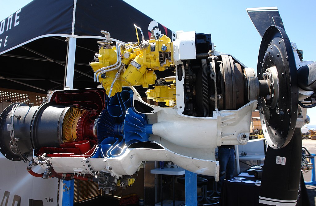
Boris Badenov ) because like I said, it's mounted backwards in the airplane and the inside of the engine is split in half.
The prop would be on the left side of this picture, and this is looking at the engine from above in a top-down view. As you can see, the central driveshaft going through the middle of the engine is split right down the middle. The blue part (Gas Generator Section) is all physically connected by the driveshaft on the right, and the red part (Power Section) is all physically connected by the drive shaft on the left, but the two halves are independent of each other.
Air travels down the duct underneath the engine all the way to the back, goes through the inlet screen at the back and works its way forward. It gets squeezed through three axial compressors and one centrifugal compressor (the blades are tapered and are more scoop shaped, like a pump). This high pressure air then gets mixed with fuel and ignited in the combustion chamber, and shot through compressor turbine. That compressor turbine is connected by the blue driveshaft back to the four compressor sections which sucked the air into the engine to begin with, and the whole process becomes self-sustaining. That's the entire gas generator cycle, and the gas generator is basically just a miniature turbojet engine... whose sole purpose is to keep itself turning.
After the hot exhaust gas is shot through the compressor turbine, it passes into the power section (the other half of the engine) and turns two power turbines before being expelled out the exhaust ducts (hence why the exhaust ducts are at the front just behind the prop). These power turbines turn the front driveshaft, which is connected to a reduction gearbox that slows the power turbine from 30,000 RPM to the 1900-2200 RPM needed to turn the propeller (for perspective, the compressor turbine spins at 45,000 RPM... so even though 15,000 RPM was lost between the compressor turbine and the power turbines, reduction gearing is obviously still needed). These power turbines are the ONLY thing that turns the prop on a PT-6, and you'll notice that the prop doesn't start to turn until very late in the start-up sequence, because you need to start the small turbojet "gas generator" first to get the hot exhaust gasses flowing through the power turbines. There's an urban legend that you can actually hold the prop stationary by hand on a PT-6 airplane during start-up, since the exhaust gasses aren't putting enough torque on the power turbines to move it. Everyone seems to know a guy who knew a guy who knew a mechanic who did it successfully, but I wouldn't recommend trying.
")
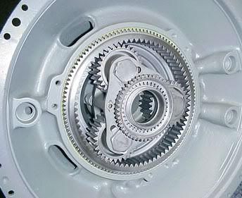
As for the reduction gearbox itself, it's a planetary gear system that looks a lot like what you'd find in the automatic transmission on a car. Here's what part of it looks like on the PT-6:
(Here's a great
website on the PT-6 with more technical details on how it works.)
The second school of thought in turboprop engine design - and one which has a healthy cult following on this site

- is the
direct-drive, as seen in the
Garrett TPE-331 (the engine found in the SA-227 Metroliner and the Mitsubishi MU-2, both of which are known to be "all that is man"). They took the more straightforward approach and said lets build a small turbojet engine and bolt a propeller driveshaft to the front of it. Problem is, since the gas-generator (turbojet) runs at ~42,000 RPM, you need a hefty reduction gearbox to slow that driveshaft down to 2,000 RPM before it reaches the prop:
It's a pretty straight-forward engine. Two centrifugal compressors (the blue part) increase the air pressure as it enters the combustion chamber (red part) and turns some axial turbines before being shot out the back as exhaust. The driveshaft which allows the turbines to keep the compressor blades turning, continues straight into the gear box. The gear box looks more complicated than the Pratt since the accessory drive gears (connecting to the yellow accessories and FCU on top) mix in the same gear box responsible for the reduction gearing (on the PT-6 the accessories are geared into the gas-generator at the back and the propeller reduction gearing is in the power section at the front).
Here's a nice cutaway of the TPE-331:
Finally you can get even smaller turbine powered engines like the Rolls-Royce
Allison C250, which was mainly intended for use as a turboshaft engine for helicopters (but you see it as a turboprop "prop-jet" conversion on some smaller GA planes as well). The Allison is kinda funny because it's basically built
around the reduction gearbox, which hangs way down below the centrifugal compressor inlet, and is what is actually connected to the output driveshaft on a helicopter. Its turbojet "gas-producer" is a cute little itty bitty thing compared to the TPE-331.
Another cool thing about the Allison that I hadn't realized until just now staring at the cutaways is that the airflow pattern is all weird. The air comes in the centrifugal compressor at the front, then gets bent around through ducts surrounding the gearbox in the middle, and completely
reverses direction into the combustion chamber where it's ignited, sent back the way it came through the turbines and bent 90 degrees up and out the top of the engine (which explains why helicopters like the Bell 206 have the exhaust duct on top. Cool!).
The Allision has two sets of axial turbines, connected to two concentric driveshafts. The N1 "gas producer turbine" shaft connects the first set of axial turbines (closest to the combustion chamber) to the centrifugal compressor via the inner driveshaft. The N2 "power turbine" shaft is hollow and surrounds the N1 shaft. It connects the second set of axial turbines to the gearbox to drive the rotors, via the outer driveshaft. This
webpage has an excellent diagram and explanation of the whole engine.
Did that help at all? Also, I think
beasly got more than he bargained for with this thread.
")
///AMG said:
^^ and just think, they did it all by candlelight with slide rules back then!
Blows my mind dude...
EDIT: I found a diagram of the reduction/accessory gearbox on the Garrett. It's part of an investigation into an incident where an Australian Jetstream 31 experienced an uncontained "bull gear" failure, sending gear fragments through the gearbox casing, out the engine nacelle wall and into the FO's side of the pressure hull. Good times!
http://www.atsb.gov.au/publications/investigation_reports/2004/aair/aair200401353.aspx
The reduction gearing does indeed look very similar to an automotive automatic transmission. It has a central sun gear (green), planetary gear assembly (yellow) and outer ring gear (orange). Click the "Factual Information" tab to see the diagram.