You are using an out of date browser. It may not display this or other websites correctly.
You should upgrade or use an alternative browser.
You should upgrade or use an alternative browser.
Teaching the Region of Reverse Command
- Thread starter SDAviator
- Start date
USMCmech
Well-Known Member
While not being technically accurate, the simplest way to describe it is that when in slow flight the airplane is starting to hang from the propeller.
Then you can get into the concept of more thrust is required to overcome the added induced drag when slower than L/D max.
Then you can get into the concept of more thrust is required to overcome the added induced drag when slower than L/D max.
thevideographer
Well-Known Member
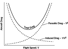
I draw a graph and show the parasite and induced drag curves, and show how total drag increases at both sides. Then I draw out the power curve with a line through the middle and explain that the back side of the curve shows that the slower you go below L/D max, the more power you need. Then I relate it to slowflight and why you need nearly full power to maintain 30kts in the 172.
Also I usually just refer to it as the back side of the power curve because when does anybody ever say "region of reverse command" outside of private pilot ground school?
Also I usually just refer to it as the back side of the power curve because when does anybody ever say "region of reverse command" outside of private pilot ground school?
USMCmech
Well-Known Member
Also I usually just refer to it as the back side of the power curve because when does anybody ever say "region of reverse command" outside of private pilot ground school?
Generally I avoid phrase "the region of reverse command" because it leads some students to think that somehow the flight controls begin to work backwards.
"Backside of the power curve" is much more descriptive.
tlewis95
I drive planes
Think about what's happening. What happens as AOA increases?
Mo lift, mo drag! One of my favorite things to discuss with students because many things that happen correlate to that.
🦈💜
Well-Known Member
I am working on my CFI rating and am having a difficult time putting the concept of the region of reverse command into a logical, easy to understand explanation. Any thoughts or ideas you guys have used to explain this would be greatly appreciated. Thanks.
I hate that term when applied to the back side of the power curve. I much prefer "the back side of the power curve", or "Operation at high angles of attack".
The explanation that I use is that for a given wing, there are two ways to increase lift: increase the speed*, or increase the angle of attack. Increasing the angle of attack increases induced drag; increasing the speed increases parasite drag. The AoA at which those two drag curves meet, where the wing is most efficient, is best glide speed / LDmax. Below that speed, increasing lift comes at the penalty of an exponential increase in drag.
If you have a power setting that results in level flight at LDmax, decreasing power will result in decreased lift. To maintain level flight, you must increase your angle of attack, which increases drag. To maintain level flight at that lower speed, you will therefore need to add power to overcome the drag you've just created.
Now, all that said, if you've done your job right with the student, you've started with the concept of angle of attack from the very beginning—since literally everything in aviation relates to it—so you won't have to "teach" the concept at all. You will be able to ask the student "Given what you know about this, what happens if I'm at LDmax and I reduce power?" ... and the student should be hintable through the entire learning experience.
Remember, he learns best who teaches himself. Teaching is simply finding the rudiments of a subject, teaching them to a student, and guiding them to figuring the rest out thesmselves.
-Fox
(* - lift is not generated by a symmetrical airfoil at 0° AoA. A cambered airfoil has the equivalent of a small positive AoA at 0° AoA, but a symmetrical airfoil must be explicitly given an AoA by the effect of the elevator. Thus, increasing the speed on a symmetrical airfoil at 0° AoA results in no increase in lift.)
Mo lift, mo drag! One of my favorite things to discuss with students because many things that happen correlate to that.
That's not entirely correct though. That's why I referenced AOA.
Houses get smaller?That's not entirely correct though. That's why I referenced AOA.
Houses get smaller?
In simple terms, higher AOA = higher induced drag. So in the region of reverse command, increase to pitch (higher AOA), and the airplane descends, rather than climbs because there isn't enough power to overcome the increased drag.
Houses will have to get bigger before they get smaller in order to get on the other side of the curve.
tlewis95
I drive planes
In simple terms, higher AOA = higher induced drag. So in the region of reverse command, increase to pitch (higher AOA), and the airplane descends, rather than climbs because there isn't enough power to overcome the increased drag.
Houses will have to get bigger before they get smaller in order to get on the other side of the curve.
Higher AoA = higher lift as well right? Induced drag is a 'by product of lift' to use the FAA definition.
Higher AoA = higher lift as well right? Induced drag is a 'by product of lift' to use the FAA definition.
It should. Unless you take it to far. Then, it stalls. I've always thought of the region of reverse command a lot like a stall. You take either one to far, and no matter what you do, you're going to lose the battle.
ahsmatt7
Well-Known Member
My best advice is to don't make this topic more than it really is. Leave graphs out of it at first. They tend to muddle up the folks who were never math or Stat savvy.
I kept it super simple. I started by explaining AOA and what it does in the normal region. (I never used the terms normal or reverse region...not even backside of the power curve...not for students at least. Only cfi and commercial guys/gals.)
Then when they understood that an increase in AOA produced an increase in lift, I would pose the question of can we increase our AOA to what ever we want and will it always guarantee us an increase in lift?
Then I bring in the concept of induced drag. At that point, they are starting to realize and understand the relationship between AOA and induced drag.
Now I go back to the four forces of flight and ask the question; if we are now having an increase in drag, what counteracts that? They usually say thrust. Which leads into how eventually we don't have enough available thrust to maintain airspeed while holding altitude. Then I throw them punch line of when we get into this high AOA and high drag situation, either we magically make more thrust, or the real only option we have is to reduce the AOA to reduce drag so we can get our airspeed back. They then catch on and realize the only way to do this is to lower the AOA which will lead into a descent.
Once they understand this concept on the ground, I'll introduce slow flight to the student pilot and for the cfi and commercial guys/gals, I have them explain to me what there doing and why they are doing it and how airspeed, aoa, thrust and altitude are all related while they are in slow flight. Specifically, how if they try to increase their aoa, they actually start to descend which is the reverse of what they commanded.
Get it, region of reverse command? See what I did there??? I
This us ally leads really nicely into stalls and stabilized approaches. Obviously two different extremes but both use the normal and reverse command regions.
Last edited:
D
Deleted member 27505
Guest
BETA!!the concept of the region of reverse command in a logical, easy to understand explanation
Seriously, see @Acrofox 's post above. I think he must have been my student at some point. Lol.
Planes stall when they go to Fargo?It should. Unless you take it to far. Then, it stalls.
Planes stall when they go to Fargo?
Everything stalls in Fargo.
inigo88
Composite-lover
Do not use this description on your students (well unless they like math), but the engineer in me has to...
Induced drag is related to alpha (AOA) because (shamelessly stolen from https://en.wikipedia.org/wiki/Lift-induced_drag#Calculation_of_induced_drag)

This is the same format for the lift equation and the drag equation, where 1/2*rho*V^2 is dynamic pressure (rho is air density and V is the velocity of the oncoming air). S is the total area of the wing (chord length * wingspan for any rectangular wing Cessna or Piper). C,Di is the induced drag coefficient, which gets its own equation:

Here CL is the lift coefficient for that wing, e is some wingspan efficiency knockdown, and AR is Aspect Ratio, which is:

Where b is wingspan and S is total wing area (above).
So finally what this all comes down to is that CL (and the 2D version, Cl) depends on angle of attack (alpha). And for every airfoil shape there are graphs for Cl vs. alpha, Cd vs. alpha, Cm vs. alpha (pitching moment), etc. Here's one for the NACA 2412 airfoil used on the Cessna 172.

Long story short... Angle of Attack (alpha) drives lift coefficient (CL). Induced drag is a byproduct of lift (and thus the generation of wingtip vorticies), so CL drives the induced drag coefficient, CDi. The the induced drag coefficient gets multiplied by the wing area and dynamic pressure (based on airspeed and density) and gets you the actual induced drag force Di, in pounds. It's really not too bad, the extra variables are just fixed values based on the shape of the wing.
Induced drag is related to alpha (AOA) because (shamelessly stolen from https://en.wikipedia.org/wiki/Lift-induced_drag#Calculation_of_induced_drag)
This is the same format for the lift equation and the drag equation, where 1/2*rho*V^2 is dynamic pressure (rho is air density and V is the velocity of the oncoming air). S is the total area of the wing (chord length * wingspan for any rectangular wing Cessna or Piper). C,Di is the induced drag coefficient, which gets its own equation:
Here CL is the lift coefficient for that wing, e is some wingspan efficiency knockdown, and AR is Aspect Ratio, which is:
Where b is wingspan and S is total wing area (above).
So finally what this all comes down to is that CL (and the 2D version, Cl) depends on angle of attack (alpha). And for every airfoil shape there are graphs for Cl vs. alpha, Cd vs. alpha, Cm vs. alpha (pitching moment), etc. Here's one for the NACA 2412 airfoil used on the Cessna 172.
Long story short... Angle of Attack (alpha) drives lift coefficient (CL). Induced drag is a byproduct of lift (and thus the generation of wingtip vorticies), so CL drives the induced drag coefficient, CDi. The the induced drag coefficient gets multiplied by the wing area and dynamic pressure (based on airspeed and density) and gets you the actual induced drag force Di, in pounds. It's really not too bad, the extra variables are just fixed values based on the shape of the wing.
🦈💜
Well-Known Member
Do not use this description on your students (well unless they like math), but the engineer in me has to...
Induced drag is related to alpha (AOA) because (shamelessly stolen from https://en.wikipedia.org/wiki/Lift-induced_drag#Calculation_of_induced_drag)
This is the same format for the lift equation and the drag equation, where 1/2*rho*V^2 is dynamic pressure (rho is air density and V is the velocity of the oncoming air). S is the total area of the wing (chord length * wingspan for any rectangular wing Cessna or Piper). C,Di is the induced drag coefficient, which gets its own equation:
Here CL is the lift coefficient for that wing, e is some wingspan efficiency knockdown, and AR is Aspect Ratio, which is:
Where b is wingspan and S is total wing area (above).
So finally what this all comes down to is that CL (and the 2D version, Cl) depends on angle of attack (alpha). And for every airfoil shape there are graphs for Cl vs. alpha, Cd vs. alpha, Cm vs. alpha (pitching moment), etc. Here's one for the NACA 2412 airfoil used on the Cessna 172.
Long story short... Angle of Attack (alpha) drives lift coefficient (CL). Induced drag is a byproduct of lift (and thus the generation of wingtip vorticies), so CL drives the induced drag coefficient, CDi. The the induced drag coefficient gets multiplied by the wing area and dynamic pressure (based on airspeed and density) and gets you the actual induced drag force Di, in pounds. It's really not too bad, the extra variables are just fixed values based on the shape of the wing.
Seriously, what good does all that gobbledygook do? It looks like line noise.
I'm not going to sit up there while stalling and try to calculate rho.
"Thank you, but I prefer it my way."
Training pilots, you need to make things intuitive. Automaticity is a product of intuition. It's intuitive to me that if I stick a flat, thin board out the window of a moving car, parallel to the direction of the car, that it will cut through the air. If I then tilt it 10° up, it will want to rise (and go back).. and if I keep tilting it, it will want to go 'back' more than 'up'. And that as I speed up, the relative forces will be greater. One doesn't need a shotgun blast full of letters, numbers and symbols to figure that out, and said shotgun blast doesn't help.
Save the math for building the airplane. ~.^
(And then, like all products of engineering, make it actually work right in the field by trial and error
")
-Fox
inigo88
Composite-lover
In simple terms, higher AOA = higher induced drag. So in the region of reverse command, increase to pitch (higher AOA), and the airplane descends, rather than climbs because there isn't enough power to overcome the increased drag.
Houses will have to get bigger before they get smaller in order to get on the other side of the curve.
Higher AoA = higher lift as well right? Induced drag is a 'by product of lift' to use the FAA definition.
Check out this old school graph for the NACA 2412 (Cessna 172) airfoil. The big S-shaped graph in the middle is lift coefficient (Cl) vs. alpha, while the flat one crossing the middle is pitching moment (Cm) vs. alpha.
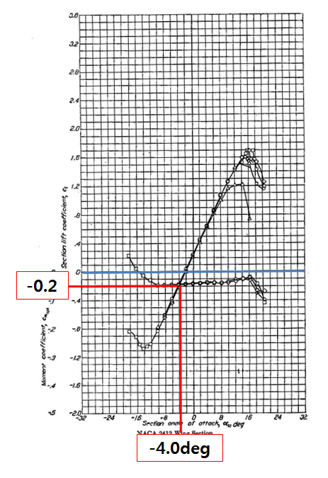
The critical angle of attack happens around 16 to 18 degrees AOA (alpha), after which the Cl drops back down. It's also cool that there's a reverse hook on the negative alpha side, so if you could push hard enough you could stall a C172 nose down at -14 degrees AOA.
")
What I didn't really make clear in that last post, is if you put all those equations together and do some algebra, you get this:

What that's saying is that your induced drag force Di (in pounds) depends on mainly the lifting force (L) squared on top and the equivalent airspeed (KEAS, Ve) squared on the bottom. L depends on Cl, which doesn't change that much. For every conceivable AOA value the Cl only goes from -2.0 to +3.6. But your airspeed range in a Cessna 172 between Vs and Vne is pretty big.
So if you're flying slow, the denominator of the fraction is small, meaning Di is mostly driven by L^2 so it should be a big number. If you're going faster the square of your equivalent airspeed makes the number in the denominator really big, which makes the value of Di really small.
This graph of total drag (and thus power required) does a good job of explaining that without all the equations. When you're slow, total drag is composed mostly of Induced Drag, which is dominated by 1/V^2 (so as V goes down induced drag goes up). As you get faster the total drag becomes mostly Parasitic Drag, which is dominated by V^2 (so as V goes up parasitic drag goes up).
Most of you probably know that (L/D)max occurs right where that total drag curve is the lowest, which also happens to be your best glide speed, and max range speed (in props). In jets it gives you max endurance.