Roger Roger
Bottom of the list
It's late now but it seems too that you're a touch fuzzy on ohm's law applied to an alternator in a full system so maybe I'll get to that tomorrow (in a hotel right now enroute to go get an airplane down south)z
I know people have already said "who cares, this won't be an interview question," but I happen to enjoy this stuff (engineering) so let's talk about it.
Here's a forum with a bunch of EE types debating the reasoning behind generating AC power and then rectifying it to DC on large transport category aircraft:
http://aviation.stackexchange.com/questions/3103/why-do-airplanes-use-ac-electric-power
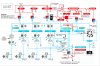
- Check out the electrical system schematic for the Boeing 737-300/400 (source):

- And the electrical system schematic for the Airbus A320 (source):
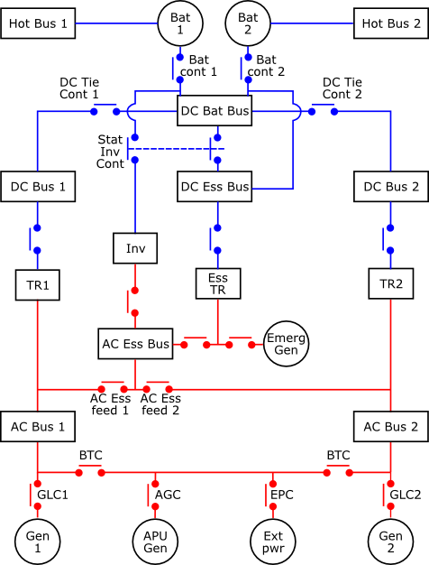
Notice that the 737-3/400 Constant Speed Drives (CSDs, Gen 1 and Gen 2) and APU Generator supply 115 V 400 Hz 3-phase AC power to the electrical system. The A320 Integrated Drive Generators (IDGs, Gen 1 and Gen 2) and APU Gen also supply 115/200 V 400 Hz 3-phase AC power to its electrical system. Both aircraft use Transformer Rectifiers (TRs) along with a backup Inverter to convert the supplied 3-phase AC power to DC.
- Why might they do this?
While for one thing, the 737-3/400 has a ton more electrical components on the AC buses (Main, Gen, Transfer, TF) using several provided voltages (115 VAC, 28 VAC). Also notice that the AC systems tend to be large components like valves, fuel boost pumps and hydraulic pumps, while the TRs downstream mainly provide 28V DC to avionics systems.
Alternating current has (at least historically) been preferred in power transmission due to the ease in which you may step up or down voltage using transformers. You'll notice the lack of any special equipment between the 115 VAC and 28 VAC buses on the 737 classic, because there are simple transformers changing the voltage between them. The A320 schematic skips transformers entirely, and many of the destination components may require voltage step downs performed by transformers.
Or maybe a lot of these important components were simply more available (or cheaper to produce) in 115VAC, since that's already the standard in the US?
- What are some advantages of 3-phase AC over single phase, and why such high frequency generators (400 Hz vs 60 Hz residential)?
http://electrical-engineering-portal.com/single-phase-power-vs-three-phase-power
http://www.electrotechnik.net/2009/11/why-are-advantages-of-three-phase.html
There are some obvious advantages of 3-phase AC vs single-phase AC that would be applicable to an aircraft electrical system. They are:
1. Three phase alternators have a higher power/weight ratio than single phase. They deliver more power per a given size and weight, so they can be lighter than their single phase counterparts. (I imagine the higher generator frequency is also advantageous to this efficiency argument and cuts down on weight.)
2. A 3-phase AC system requires 25% less wiring to transmit the same amount of power over a given distance than a single phase system. This further cuts down on weight!
3. 3-phase AC motors are self-starting while single phase AC motors are not. This may be advantageous to some of the pumps and valves which run on AC power, along with the Integrated Drive Generators (IDGs) on newer aircraft which work double duty as both starter motors and AC generators.
A disadvantage of 3-phase AC is the greater complexity, and for AC in general, that frequency and phase must be synchronized between all AC generators in order to feed a common bus.
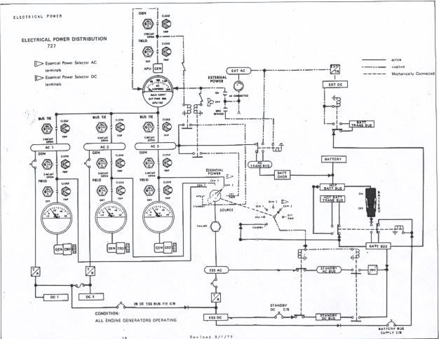
One need only look at the electrical panel on the Boeing 727 flight engineer's station and see three individual "FREQ" knobs where you literally have to tune the frequency of each AC generator before tieing the AC buses together to realize that this is indeed a complicated system. Fortunately for everyone (except @Adler) this process became automated on later aircraft.
Admittedly I'm not an Electrical Engineer so some of this might be bogus, but I figure it's a good start. I know somebody will argue that High Voltage DC transmission is a thing and that DC-DC converters can transform voltages as efficiently as AC transformers can... But I believe this relatively recent revival in DC is based on semiconductor technology, so given the historical perspective of the big aerospace companies designing the first jet airliners in the 1950s and 60s I believe my reasoning is sound.
Also, I know at least some of you do have EE degrees (but probably don't like to type a lot), so I hope you guys weigh in if you feel the need... And @Roger Roger, because your input is ALWAYS good.")
If the alternator doesn't have the entire electrical load, then the battery is discharging. Did you not learn what a discharge on the ammeter means? If you're showing -5A with the alternator on, you'll still eventually lose the electrical system. Do you understand what it is you are saying when you say the alternator supplies the electrical load and charges the battery, or are you just saying what you were told to say? (rote memory is so worthless)I've been doing my research up through some of the advanced systems books by Jeppesen about the basic understandings of electrical systems and then I start trying to read up on AC/DC systems and I get lost in translation through various links on the Internet. I was never taught about the alternator having all the electrical load but then CFIs out there post this stuff on the Internet just confusing me. I teach basic electrical system like alternator supplying the electrical load and charging the battery etc....but I have yet to have a checkride go beyond that.
These questions might seem out of this world for someone with no 121 experience but why is it on almost every interview gouge I read? I don't wanna just assume they just want the answer and no explanation and botch the interview. That's kind of why I'm here asking for experienced help. Systems (like many colleagues I have) is not my most powerful strength at all...not afraid to admit it.
What is a basic understanding? The drawings on YouTube/PHAK or the full blown drawings from a POH? Forgive me for asking a foolish question in your eyes but I'd rather ask than just assume and be wrong. Sorry dude.
That is correct. Those are the battery's only purposes. Think about it, the batter is all but out of the system once charged anyways. So the alternator puts out 14V and the battery is probably 12.8-13.0 when charged. It is a lower voltage, so the battery cannot provide anything to the system unless the system voltage drops. (Alternator drops offline(0V) or a really high load with resistance causing voltage drop.)Then I read my company AOM and it clearly states (which is what I have to teach students) that the alternator supplies output and the alternator just charges the battery...as if the battery has no use other than to start the engine and supply electrical power in the event of an alternator failure?
The alternator should be carrying 100% of the load. If you turn something with a very high amp draw on like maybe both the landing and taxi lights, you'll see a momentary discharge from the battery(ammeter to like -10 then 0 in less than a second) as the resistance from the lights drops the voltage until the alternator increases it's output. That said, once the engine is running, you could remove the battery from the airplane and everything would function normally. When you turn those lights on now, they'd just come on a bit dim for that 1/2 second while the alternator picks it up. You can almost think of the battery as more of a capacitor once the engine is running. Actually you can always think of a battery as a very slow drain capacitor.So which one is it? The first one makes sense to me that the battery would supply the electrical power while the alternator supplies the battery juice to keep it fully charged and if the alternator fails the electrical load would be the same instead of jumping ship? Then I read someone state that the alternator holds the electrical load and when you switch something on to add to that load, it will start it's supply from the battery and then transition to the alternator? Maybe I've confused myself more in this process but so many links and articles are posting two completely different answers.
Just know that Alternating current, AC, is a sine wave function and Direct current, DC, is a flat voltage. Not that important to know, but typically aircraft AC is 120V @ 400Hz, so the voltage is actually a sine wave of +120V to -120V and changes between them 400 times a second. DC is simply positive voltage, so just +12V, which is why it's much better for sensitive electronics. You can go between the two with inverters(DC->AC) and rectifiers(AC->DC). Transformers change voltages, so a TR(transformer rectifier) changes AC power to DC and changes the voltage. Typically AC is higher voltage than DC so you're probably transforming down with a TR. You can actually change voltage with a half wave rectifier and no transformer, but I don't think that is relevant to airplanes.Also, I know interviewers like to ask about AC to DC and DC to AC....which I know about rectifiers and inverters ...but why? AC power is more useful to have than DC because it supplies the more precise amount of electrical load instead of DC always supplying a certain load that could strain the loads over time. In longer fuselage aircraft such as regional jets, narrow and wide bodies though, I read that DC is better? I'm not sure why but I would assume because it has a longer distance to travel, you wouldn't want AC traveling over all of that?
The battery will be capable of producing more amps for a short period of time. Typical cranking amps for a starter is 300 and up. The alternator has a flat limit, on most piston airplanes something from like 30-70. The total amps the alternator is important to know what it's total load is, so you don't try to pull 100amps from a 70amp alternator. The battery is usually ratted for cranking amps and a longer term draw. The more cranking amps it can put out the faster it can spin the starter and the more amp-hours it's rated at, the longer it will last given an alternator failure. After an engine start, the battery is somewhat depleted. The alternator will then start to charge the battery but only up to it's amp limit, so it will take a few minutes to replenish what the battery just expended in a few seconds. This is why you will see the ammeter typically show charging, or a positive value right after a start and for a few minutes afterwards.Last question, when drawing the system you explain the volts your alternator has and battery has (which alternator is more because it will charge the battery) but then why does it matter about stating the amps on the battery and alternator. Again, my AOM only states how many amps the alternator has but not the battery. The alternator would have more amps because it would need to be able to take the load of the entire system and charge the battery....correct?