tcco94
Future GTA VI Pilot
So I've been looking and trying to get a jump start on studying for my interviews...mainly this is for skywest.
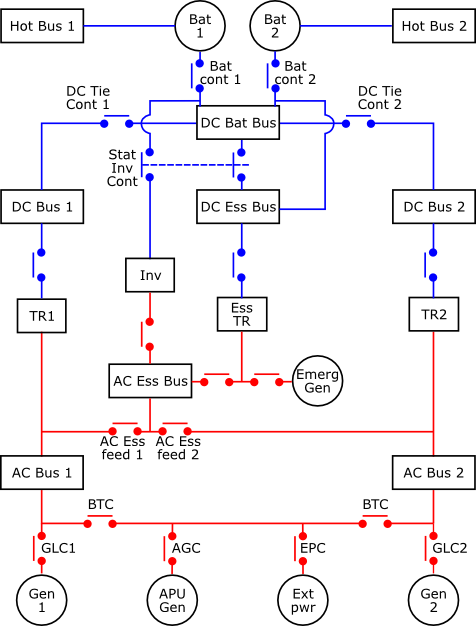
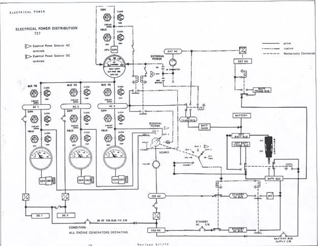
In doing my research I've learned something and confused my brain a lot. I've read on various websites stating that the battery supplies all the electrical power and the alternator just charges the battery in the process. Also, the alternator amps are just a projection of how powerful the alternator is...but in fact, the alternator will only supply amps to the battery for charging and system that is needed at that exact moment. The alternator just has the ability to supply that many amps, if needed.
Then I read my company AOM and it clearly states (which is what I have to teach students) that the alternator supplies output and the alternator just charges the battery...as if the battery has no use other than to start the engine and supply electrical power in the event of an alternator failure?
So which one is it? The first one makes sense to me that the battery would supply the electrical power while the alternator supplies the battery juice to keep it fully charged and if the alternator fails the electrical load would be the same instead of jumping ship? Then I read someone state that the alternator holds the electrical load and when you switch something on to add to that load, it will start it's supply from the battery and then transition to the alternator? Maybe I've confused myself more in this process but so many links and articles are posting two completely different answers.
Also, I know interviewers like to ask about AC to DC and DC to AC....which I know about rectifiers and inverters ...but why? AC power is more useful to have than DC because it supplies the more precise amount of electrical load instead of DC always supplying a certain load that could strain the loads over time. In longer fuselage aircraft such as regional jets, narrow and wide bodies though, I read that DC is better? I'm not sure why but I would assume because it has a longer distance to travel, you wouldn't want AC traveling over all of that?
Last question, when drawing the system you explain the volts your alternator has and battery has (which alternator is more because it will charge the battery) but then why does it matter about stating the amps on the battery and alternator. Again, my AOM only states how many amps the alternator has but not the battery. The alternator would have more amps because it would need to be able to take the load of the entire system and charge the battery....correct?
I might be overthinking how difficult these questions are but I don't want to know the answer...I really want to understand the why so I can confidently explain and understand it.
My AOM's are for PA28 and PA44


")
