What is this????

Please, someone post PHAK or another aerodynamics slide quick! I've got other homework to do right now!

http://en.wikipedia.org/wiki/Stall_strips

This is accurate.

What would make you think aileron buffet is useful to stall recognition? I assume you're familiar with a stick shaker? Or with turbulent air shaking the elevator by striking the tail in our smaller GA aircraft? In other words, elevator disturbances are what notify the pilot of stall; not ailerons.
 
The Wedge is post '84. It is suppose to help with stall characteristics.
 
Many aircraft have stall strips to induce buffeting over the flaps or ailerons to create the sensation before the stall.

I agree that this doesn't make sense. You wouldn't want to create turbulent flow over your control surfaces. You want laminar flow to maintain control surface effectiveness (right?). That's the whole reason stalling at the wing roots first and not the tips is a sought after characteristic by aerospace engineers, because flow separation at the wing roots first allows the ailerons to remain effective because flow separation at the tip hasn't yet occurred.

Furthermore, while you always have that "reverse flow" adverse pressure gradient force, when flow separation occurs trailing edge pressure drops even more and you get a major increase in drag, called pressure drag due to separation. So you get this large increase in drag at flow separation in addition to the characteristic loss of lift from a stall. Considering Moment of Inertia, if you apply a large drag force vector at the wing tip (opposing forward motion) vs. at the wing root, what happens? Your lever arm at the tip (from the center of the fuselage/coordinate origin when looking at a top-down view) is way longer, so your rotational Moment is going to be higher for the same drag force. (Hence why we don't put the most weight in the baggage compartment, due to the longest lever arm from our datum creating the highest moment.) Thus, I'd imagine that yaw z-axis rotation in a tips-first stall would be much more dramatic then at the roots, and lead to easier inadvertent spin entry... Thoughts?
 
You want laminar flow to maintain control surface effectiveness (right?).

You don't want separation. Whether the boundary layer flow is turbulent or not will not render a control surface unusable; separation will. Consider a 172 or other trainer aircraft. These aircraft don't have laminar flow, yet you can still use their controls. In fact, as was pointed out earlier, a turbulent flow has a higher kinetic energy than laminar. Turbulent flow's increased KE is what keeps the boundary layer attached farther aft on the airfoil than laminar flow, thereby keeping an aft control surface effective at higher angles of attack.
 
Stall strips are there to modify the stall charactoristics of a wing. They vary in location with the aircraft design. Sometimes they are located at the wing root. Sometimes they are not. I have personally seen them out in front of the ailerons where one wouldn't expect them.

The simplest answer is that stall strips will be placed where they are needed based on the manufacturers flight testing.
 
http://forums.bonanza.org/forum_posts.asp?TID=2274

In his book ("They Called Me Mr. Bonanza") Larry Ball states (when discussing the changes to the A36 that occurred in 1984) that "The leading edge wing vortex generators (originally developed for the F33C) greatly improved stall characteristics."

Not that this is a definitive source on the subject, but it shows trend -- http://www.studentpilot.com/interact/forum/printthread.php?t=20298

Maurus - can you give an example? I've never seen an aircraft with them out over the center of the ailerons. I've seen them out over the first 20-40 percent of the ailerons, such as a piper saratoga. But, upon further investigation, you'll notice that the wing is composed of two different airfoils. The stall strips are there to make the stall uniformly progress outward from the inboard airfoil designed to stall at a much lower AOA than the outboard. Essentially this prevents the pilot from getting the inboard airfoil too deep into the stall regime.

Find me a wing where they are located on the outboard wing where there is no notable difference between the two sections of the wing. You won't, but I owe you a case of your favorite brew if you find one. :)

Again, stall strips force a wing to stall, they have the opposite effect of vortex generators.
 
No, No, ... no...Some aircraft have strips to deepen the stall at the root ... Please, someone post PHAK or another aerodynamics slide quick!

Will a report from the navy air development center work?

http://www.dtic.mil/cgi-bin/GetTRDoc?AD=ADA235994

page56 said:
By using a stall strip the flow is disturbed near the root such that root area stall is induced first. This method is not preferred because it limits rather than improves CL... It turns out that the use of stall strips is usually a design "after-thought" to improve stall warning cue characteristics found to be unsatisfactory during flight testing.
 
Maurus - can you give an example? I've never seen an aircraft with them out over the center of the ailerons. I've seen them out over the first 20-40 percent of the ailerons, such as a piper saratoga. But, upon further investigation, you'll notice that the wing is composed of two different airfoils. The stall strips are there to make the stall uniformly progress outward from the inboard airfoil designed to stall at a much lower AOA than the outboard. Essentially this prevents the pilot from getting the inboard airfoil too deep into the stall regime.

The Diamond DA-20 has a stall strip in front of both ailerons. It is not located in the middle of the aileron but the flight testing seems to have shown the need for the strips where they are.

1904649.jpg


main.php
 
The Diamond DA-20 has a stall strip in front of both ailerons. It is not located in the middle of the aileron but the flight testing seems to have shown the need for the strips where they are.

1904649.jpg


main.php

The DA-20 is a versatile plane. According to a previous boss of mine when he tried his first power on stall he did a loop instead of actually stalling. My guess is that is why the strips are where they are located.
 
It is not located in the middle of the aileron but the flight testing seems to have shown the need for the strips where they are.


Yes, it's located at the very start of the ailerons, like the saratoga I mentioned. I suspect for a similar reason, but without seeing the aircraft up close it's hard to tell. With the saratoga there is a notable difference in the outboard vs the inboard airfoils. Take a close look at the DA-20 and I suspect you'll see a difference in the taper, camber, and chord or in some combination of the three. It may be very noticeable or only slightly.

When two different airfoils are used, if the inboard stalls at 12 degrees and the outboard airfoil at 16 degrees, an unwanted stall progression can occur. The uniform stall progression seen in a Hershey bar wing is always desired; that is, uniform and progressive from root leading edge to tip trailing edge. A stall strip where the 16 degree airfoil starts can bring it to say 14 degrees. Now we have uniform and progressive stalling airfoil, like we want.

Much of this is, of course, speculation. With no technical data on the aircraft or one to look at up close I'm left with offering what a designer aims to see in stall behavior.

Though I'll mail you a 6-pack for giving me another aircraft to research. I'm obsessed with this design stuff!!! What's your favorite brew?
 
Believe it or not my first post does agree with you. Design and flight testing will dictate the actual need and location for the stall strip. To say it is needed at the wing root to cause a stall early at the root would actually be a fallacy as it isn't always true as seen here.

Let me know if you find out exactly why the strip is where it is located.

These types of conversations are always great to have. Been able to teach beyond what a "normal" instructor may be able to teach as a result.

I'm a Killians person but any Amber brew is good. :)
 
You don't want separation. Whether the boundary layer flow is turbulent or not will not render a control surface unusable; separation will. Consider a 172 or other trainer aircraft. These aircraft don't have laminar flow, yet you can still use their controls. In fact, as was pointed out earlier, a turbulent flow has a higher kinetic energy than laminar. Turbulent flow's increased KE is what keeps the boundary layer attached farther aft on the airfoil than laminar flow, thereby keeping an aft control surface effective at higher angles of attack.

D'oh! It was late and I was confusing general turbulent flow with the transitional turbulent flow that immediately precedes separation in a stall. Thank you for explaining that.

I'm taking intro to fluid mechanics so hopefully I'll have something better to contribute when we reach that chapter haha. I was also getting confused by the "Laminar Flow airfoil" vs. "Turbulent Flow airfoil" nomenclature, but this cleared it up:

fig14.gif

As you can see there's always laminar flow at the front of an airfoil (in fact, there's a stagnation point at the leading edge where velocity=0 and pressure is at a maximum due to the air in front of the wing "piling up"... so the stagnation point that Aerodynamics for Naval Aviators refers to is at the separation point and I assume due to the reverse flow pressure gradient causing V=0 at that point as well). The differentiation between a laminar flow wing (Cessna 177) vs. a turbulent flow wing (Cessna 172) seems to be how far back the transition point is, where laminar transitions to turbulent - and on a "Hershey Bar" wing that must be very close to the leading edge. I would also guess that to have true laminar flow you need to make the wing very smooth to minimize skin friction drag, i.e. countersunk rivets, etc.

I guess I wasn't understanding why turbulent flow (higher KE=1/2mv^2) was desirable since you always hear about laminar flow being desirable in aerodynamics due to the lower skin friction drag. What I didn't really understand was that the boundary layer velocity is less than the free-stream velocity, which is why it's susceptible to that adverse pressure gradient to begin with. This wikipedia article (from Boundary Layer) helped a lot:

At lower Reynolds numbers, such as those seen with model aircraft, it is relatively easy to maintain laminar flow. This gives low skin friction, which is desirable. However, the same velocity profile which gives the laminar boundary layer its low skin friction also causes it to be badly affected by adverse pressure gradients. As the pressure begins to recover over the rear part of the wing chord, a laminar boundary layer will tend to separate from the surface. Such flow separation causes a large increase in the pressure drag, since it greatly increases the effective size of the wing section. In these cases, it can be advantageous to deliberately trip the boundary layer into turbulence at a point prior to the location of laminar separation, using a turbulator. The fuller velocity profile of the turbulent boundary layer allows it to sustain the adverse pressure gradient without separating. Thus, although the skin friction is increased, overall drag is decreased. This is the principle behind the dimpling on golf balls, as well as vortex generators on aircraft. Special wing sections have also been designed which tailor the pressure recovery so laminar separation is reduced or even eliminated. This represents an optimum compromise between the pressure drag from flow separation and skin friction from induced turbulence.
 
As you can see there's always laminar flow at the front of an airfoil

This is sort of like saying that airflow in the atmosphere above us is laminar flow. This may or may not be true, but I question it's relevance. When speaking in terms of laminar or turbulent flow around an airfoil we are referring to the flow characteristics of the boundary layer.

so the stagnation point that Aerodynamics for Naval Aviators refers to is at the separation point and I assume due to the reverse flow pressure gradient causing V=0 at that point as well).

Yes. Separation of the boundary layer occurs following the stagnation, V=0, and the airfoil section aft of this stagnation point, where the boundary layer is no longer attached, is referred to as stalled.

I would also guess that to have true laminar flow you need to make the wing very smooth to minimize skin friction drag, i.e. countersunk rivets, etc.

Here (emphasis added):

Aircraft Performance and Design by John D. Anderson said:
Ever since Ludwig Prandtl in Germany introduced the concept of the boundary layer in 1904, it has been recognized that two types of flow were possible--laminar flow and turbulent flow--in the boundary layer. Moreover, it was known that the friction drag is higher for a turbulent boundary layer than for a laminar boundary layer. Since mother nature always moves toward the state of maximum disorder, and turbulent flow is much more disorderly than laminar flow, about 99% of the boundary layer along the wings fuselage of typical airplanes in flight is turbulent, creating high skin-friction drag. However, in the late 1930s, by means of proper design of the airfoil shape, NACA developed a series of laminar-flow airfoils that encouraged large regions of laminar flow and reduced airfoil drag by almost 50%. Such a laminar-flow wing was quickly adopted in 1940 for the design of the new North American P-51 Mustang. However, in practice, these wings did not generate the expected large laminar flow. The NACA wind tunnel experiments were conducted under controlled conditions using models with highly polished surfaces. In contrast, P-51 wings were manufactured with standard surface finishes that were rougher than the almost jewel-like wind tunnel models. Moreover, these wings were further scored with scratches in service. Roughened surfaces encourage turbulent flow; even insect smears on the wing can cause the flow to change from laminar to turbulent. Hence, in practice, the laminar-flow wing never created the large regions of laminar flow required to produce the desired low level of skin-friction drag. However, totally unexpectedly, the laminar-flow airfoil shape turned out to be a very good high-speed airfoil. It had a much higher critical Mach number than a conventional airfoil did, and hence it delayed the onset of compressibility problems encountered by many high-speed airplanes in the early 1940s. A technological development from the era of mature, propeller-driven airplanes resulted instead in paving the way for the next era--the era of the jet-propelled airplane.

Apologies for the length, figured you might find that interesting however. :)


What I didn't really understand was that the boundary layer velocity is less than the free-stream velocity, which is why it's susceptible to that adverse pressure gradient to begin with.

Friction of the surface slows the boundary layer similar to other physical friction forces you've studied. Which, as you might conclude, is why more KE equates to a greater distance of travel before stagnation.
 
Believe it or not my first post does agree with you. Design and flight testing will dictate the actual need and location for the stall strip.

I remember. Though I'm not going to say you didn't confuse me with this pseudo disagreement. Are you testing me captain!!!? Well just you keep in mind, you didn't find an aircraft that met my stipulations. ;) And I don't think one exists outside of maybe some test aircraft.

If an aircraft uses two different airfoils (which I suspect is what your example aircraft has done) the change from one type to another typically occurs approximately where the aileron section of the airfoil begins. That would explain the use of stall strips at that point. I've not read or seen anything that would explain stall strips being positioned where the vortex generators of this topic thread are placed on the Bonanza. That is, centralized in front of the ailerons.

I'll let you know if I find anything out though. Meanwhile, if you've got one of these on your field, go take a look at it. Look for changes in thickness, camber, and chord outboard versus inboard of the stall strip. If there's a change in airfoil at or near that point, that's likely why they are there. If not, well hopefully I'll find something.
 
Well after all of that I walk into the shop today and see stall strips on the tips of one of our Arrows. Uhg, back to the drawing board. It's an old t-tail arrow, if anyone has informaiton or a source it would be much appreciated. I've no clue why they are there except that I note they are positioned lower on the airfoil than the inboard set of strips. I wonder if it's to prevent the wing from getting too deeply stalled.

Oh well, will report if I discover anything. You win Maurus. LOL :(

Haha it happens. That is why we are here. To learn. This is a good thread. Lots of tech stuff and discovery.

Mind taking a pic of the stall strip on the arrow?

Here is another thing about stall strips. Some aircraft only have one total instead of a matching strip on the other wing. If the only reason for a stall strip is to start a stall at the wing root why would a manufacturer only install it on one wing?
 
This is sort of like saying that airflow in the atmosphere above us is laminar flow. This may or may not be true, but I question it's relevance. When speaking in terms of laminar or turbulent flow around an airfoil we are referring to the flow characteristics of the boundary layer.

Yes. Separation of the boundary layer occurs following the stagnation, V=0, and the airfoil section aft of this stagnation point, where the boundary layer is no longer attached, is referred to as stalled.

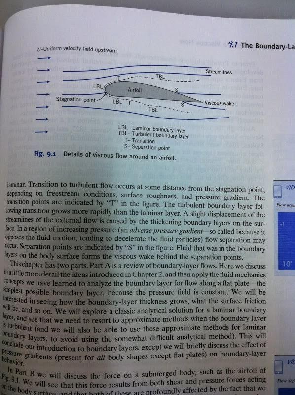
I was basing my question off this page from "Introduction to Fluid Mechanics," Pritchard, Philip J, 8th ed (pp. 423):

BoundaryLayerfromIntrotoFluidMech.jpg


Now considering how un-aerodynamic the "Hershey Bar wing" of our beloved training airplanes actually is, I could conceivably see the transition from LBL to TBL being extremely close to that forward stagnation point at the leading edge (add to that skin friction from dead insects, scratches, rough paint and round-head rivets and I could easily see where Anderson's 99% figure comes from!), but this diagram is what led me to ask the question.

shdw said:
Apologies for the length, figured you might find that interesting however. :)

No apology necessary, that's awesome!!! That's the same author as Introduction to Flight I quoted earlier (sorry I said "Mark Anderson", that was the instructor name of the course I used it for... confusing!). John D Anderson is the curator of aerodynamics at the Smithsonian National Air and Space museum, and I love all the aviation history tangents he takes in his books. :)

Also highly recommended is "Aircraft Design: A Conceptual Approach" by Daniel Raymer, or pretty much any of the other AIAA published textbooks. (I haven't even read this one all the way through yet, but it's fantastic.)

Thanks again for the hand-holding through the Boundary Layer questions. This would be an appropriate time for the :beer: smiley, but it's gone. :(
 
Back
Top