I had this question when I was a CFI!

SpiraMirabilis

Possible Subversive
I love XKCD:

airfoil.png
 
So what's the correct answer?
I said that although I didn't know for sure that I suspected that while if upside down an airfoil might produce "negative lift" that it is still producing energy and that the elevator could be used to pitch the nose such that by changing the AoA a level attitude might be able to be maintained, but that of the only aircraft I have flown that was designed to fly prolonged periods inverted (Extra 300) has a symmetrical airfoil (the MA 15S airfoil) rather than the assymetrical one that is shown in the ocmic above so this particular explanation might not be completely applicable.
 
The problem is the general description of how a wing produces lift because of the longer distance traveled is wrong and needs to stop being taught.

Okay.

So. Again.

What's the correct answer? I'm not being a jerk. I don't know the answer and would like to.
 
BTW, on the link above you are looking at the last page in the series from NASA. It may be beneficial to hit the "prev" arrow at the bottom several times and start from the beginning.
 
Lift is actually the result of normal pressure and shear stress distributions all over the wing surface. This is a result of wing geometry, angle of attack, speed of the oncoming air, etc. There is a Newtonian explanation (Conservation of Mass, Momentum and Energy which together result in the famous Navier-Stokes partial differential equations), an explanation relating lift generation to the circulation of air around the airfoil (Kutta-Joukowski Theorum) and the Bernoulli explanation which we're all the most familiar with.

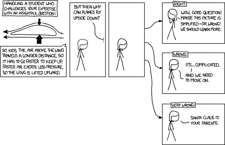
The Bernoulli equation works great and it's true that when air over the top of the wing speeds up the pressure goes down. The problem with this explanation is when people start spouting the "Equal Times" explanation, where they say "the air going over the top of the wing has to catch up to the air below it, and the path it travels is longer because the top is curved and the bottom is not, so it has to speed up and thus the pressure on top drops because of Bernoulli!" <-- The end is correct, the rest is bullcrap. :)

The truth is the air at the bottom never catches up to the air at the top, and here's a great animation of what actually happens. A better explanation of why the air speeds up on top is a physical geometric one. All those parallel lines of air are called "streamlines," and when the streamlines are diverted over the top of the airfoil they bunch up and squeeze closer together until they pass the trailing edge. The Conservation of Mass equation does say the same amount of mass has to leave out the back as what comes in the front (just not that the top and bottom have to exit at the same time), so as those streamlines bunch up the area between them decreases and the only way to satisfy conservation of mass is to speed up the air. Bernoulli then tells us that increase in the speed must decrease the pressure. An easier physical analogy is the venturi in a carburetor, because its actual walls contract, speeding up the air in the throat (and thus decreasing the pressure) because of Conservation of Mass (the same amount has to go out the back as what comes in the front). When the throat widens up again and its area increases, the air slows back down to its original speed at entry.

This relationship between air velocity and area is explained mathematically by the Continuity Equation: V1A1 = V2A2
(assuming incompressible flow which means we can neglect air density)

The streamlines bunching together on the upper surface of the airfoil is analogous to the venturi example, only instead of physical walls constricting the air it is the streamlines of other flowing air above and its momentum that act as a barrier. The result is the same: Area goes down so velocity must go up (continuity equation). Velocity goes up so pressure must go down (Bernoulli equation).

So why can an asymmetric airfoil fly upside down?

I was curious about this myself. I knew the answer lay somewhere in the wing geometry and the deflection of the oncoming air (angle of attack = angle between the chord line and the free stream oncoming air). When you fly inverted you have to shove a lot of forward stick to maintain level flight, and furthermore you have to shove a lot more forward stick in say a Cessna with a flat-bottomed airfoil than you would in an Extra 300 with a symmetrical airfoil (this is assuming you don't mind the engine stopping on the Cessna!). Why is this? And come to think of it, why does the symmetric wing on the Extra generate lift at all (even upright), and why do you need a greater pitch angle to keep it in level flight?

I hit the jackpot and found an outstanding article titled An Aerodynamicist's View of Lift, Bernoulli and Newton, written for The Physics Teacher magazine by Charles N. Eastlake - an Aerospace Engineer and a pilot.

Eastlake explains inverted flight and symmetric wings on pages 6-7 of the document (pp. 171-172), and I recommend checking out figures 3, 4 and 5. He says the key to all these questions is the location of the stagnation point. The stagnation point is the point on the airfoil where the oncoming air velocity=0 - on the leading edge the air has hit a wall and has to split two ways, above the wing and below it. There is also a stagnation point at the tip of the trailing edge, because the leading edge blocks any oncoming air from hitting it.

In all three cases of the flat-bottom airfoil, the symmetric airfoil and the inverted airfoil, the stagnation point at the leading edge is is located in a different place. In the first two cases the stagnation point is on the lower surface of the airfoil... but on the symmetric airfoil it's farther from the chord line on the bottom of the wing. This is why you need more aft stick to keep the nose up and maintain altitude with a symmetric airfoil, because you are basically tricking the wing into putting the stagnation point in such a place that the air flowing over the top is forced through more deflection and a resulting narrower path of bunched streamlines.

In the case of the inverted wing, you are pushing stick forward so that the oncoming air actually hits the top of the airfoil, not the bottom. With the resulting stagnation point on the upper surface of the wing, the air that splits over the leading edge and turns to follow the lower surface faces more deflection and the streamlines bunch up on the lower surface of the wing, not the upper. Thus we have actually tricked the air into thinking the top of the wing is the bottom, and the bottom is the top! The wing flies along normally upside with the high and low pressure areas exactly opposite of where we are taught they should be.

Thus even though the shape of a flat-bottom airfoil helps create more efficient lift, we the pilots are ultimately the ones in control of the constantly changing shape of the pressure distribution over the wing, by controlling angle of attack, airspeed and wing geometry (with things like flaps and slats). For every wing shape attempted there are graphs showing AOA vs. Lift Coefficient (CL). For every AOA there is a corresponding value for CL, and they are all different! When you start adding flaps to the mix, you get a different curve on the graph for each flap setting! What a nightmare!

I hope that helps. It's a hard concept to explain by writing and I hope you take a look at Eastlake's article above, and compare Fig. 4 and Fig. 5. Compare the two pictures and note where the bunched up "crowded together" streamlines appear in each case, and I think it will make sense. Hint: They're in the same spot, but one wing is upright and the other is upside down!

I'm glad to see fish314 in this thread, and I bet shdw would have some good insights too if he would care to weigh in. Then we can make it a total aerodynamics nerdfest. :D
 
For one thing, the drawing is a little misleading. Most airplanes have a much more symmetrical airfoil shape than in the sketch. It's typically drawn like the flat bottom Clark Y shape to emphasize the purpose of the shape. Some aircraft, like the Piper taildraggers use the USA 35B (Clark Y shape), but they will have very very limited inverted abilities. Here's the USA 35B airfoil:
USA_35B_-_All_Rag_Wing_Pipers.jpg


Many other aircraft use a more symmetrical airfoil.

For example, almost every Cessna single airframe uses the NACA 2412 airfoil. Here's what it looks like.
NACA_2412.png


While not a fully symetrical aerobatic shape, you can see that inverting it and simply using the appropriate angle of attack would generate lift the same way as when upright (to a limited degree).

Aircraft actually designed for sustain inverted flight have an even more symmetrical airfoil, so that performance is nearly equal in either orientation.

Take a look at the NACA 1412 airfoil used on the Decathlon, a common aerobatic trainer and used in sporting aerobatic competitions.
NACA_1412_-_8KCAB_Decathlon.jpg


In another example, the Pitts S2 aerobatic biplane uses the NACA 63A015 on the top wing and the NACA 0012 on the bottom wing, notice how balanced they are:
terms.jpg


800px-NACA_0012.svg.png


One other note, an aircraft going inverted but still maintaining positive G's, like in a 1G aileron roll, or in a 4G barrel roll, or a loop (where you might go zero G floating over the top, but not negative, and then a 4G pull through the bottom) does not need inverted performance from the airfoil. The angle of attack remains positive throughout the entire maneuver. That's why you could loop or roll a Clark Y just fine. However, try to roll it over on it's back and push the nose up and sustain inverted flight and you're probably going to be very disappointed with the results.
 
Wouldn't a combination of Bernoulli's Principle and Newton's Third Law suffice? I can't regurgitate all this NASA stuff!
 
Wouldn't a combination of Bernoulli's Principle and Newton's Third Law suffice? I can't regurgitate all this NASA stuff!

Dont try to explain it any more technically than you can understand it. For all you know your inspector may hold a masters degree in aeronautical engineering... and if you want to open that door then you're inviting the trouble. Keep your explanation simple. Draw a venturi, explain Bernoulli, cut the venturi in half - wow, it's a wing!
That's all you need to know.

Also, Bernoulli "is" Newtonian physics, it's not an either/or.
 
What's the correct answer? I'm not being a jerk. I don't know the answer and would like to.

Lift is generated by the production of circulation around the wings, by which some velocity is added to the stream-wise velocity over the top of the wing, and some is subtracted from the velocity beneath the lower wing surface.

If a student asked, this would be where I'd base my answer. Realizing that circulation about the airfoil exists can help put the mind at ease and make it more believable that equal transit theory is incorrect. You can support it with: http://www.grc.nasa.gov/WWW/k-12/airplane/wrong1.html

The most accurate answer I'm aware of, though less believable in my opinion, is there exists no logical reason why the two separated particles need to meet again.


rframe said:
Dont try to explain it any more technically than you can understand it.

inigo88
And this is exactly why I'd never think to mention the Kuta condition, or anything else of this sort. For one, the Kuta condition is often misrepresented. Really Martin Kuta merely said that if the real world makes it happen this way, it should happen this way mathematically. He didn't discover the existence of leading/trailing edge stagnation points, this was known through wind tunnel tests long before. Here's how Chris Carpenter, in his book Flightwise, puts it:

Flightwise said:
The Kutta condition applies a delightfully obvious and commonsense answer to this question: it says that, just as nature adds exactly the right amount of circulation to ensure separation at the trailing edge, so mathematically the determining factor must be exactly the same.

Now it's all well and good that I can explain this in words, but as rframe suggests, what if my examiner has a degree in the field? Subsequently giving me the formulai and an example, questioning me further after my boastful reply to a simple question. Guess what, I'd be screwed. Keep it simple, equal transit theory is incorrect because there is no logical reason for it to be correct. If you'd like to mention circulation, great, but do yourself a favor and stop there. :)


Inigo, perhaps you can verify this. I've been trying to in my readings, but am unable to find a verbatim response that I'm looking for. The Kuta condition only applies to certain flow condions, right? If so, do you know the name of the flow so I can research it?

I ask because I know the rear stagnation point does not remain at the tip as stall angles are approached. Instead it creeps forward along the upper surface of the wing. So it would seem obvious that the Kuta condition does not apply at this time, unless I'm missing something. Thanks in advance.
 
Simple solution: Fly upside-down more....

No... really.

First, get rid of the notion that you need an inverted fuel & oil system. This is only for sustained inverted flight. All airplanes can fly upside-down (structurally permitting). Maintaining altitude is a different story...

To keep it simple, look at two different airplanes, but not too different where your point gets lost. The 7KCAB Citabria and 8KCAB Decathlon are great examples. At the very least they are essentially identical airframes aside from one exception, the wing. The best part is, if you get the chance both aircraft have inverted fuel & oil systems which allow the student to get up-close & personal with inverted flight.

The Citabria has the classic flat bottom with the max camber occurring closer to the leading edge with a constant taper to the training edge (you draw this). Then you have the Decathlon with it's semi-semetrical airfoil, with a camber on the bottom of the wing as well as the top. This, along with less dihedral allows the Decathlon to perform better with negative AOA.

To keep it simple I'm just going to talk about AOA.

An airplane is able to fly upside down because of negative AOA. Airfoil shape will decide how efficiently this will happen. Airplane systems will limit how long this will happen.

Look at the difference in airfoil performance with negative AOA. An airplane with a non-symetric airfoil will require a larger neg AOA to achieve the same amount of lift at a pos AOA.

You just take the 4 forces picture, turn the airfoil or airplane upside down and keep the forces in the same place. It really is that easy. Convincing someone that it really does work, that's another story... This is when you start to discuss control pressures and inputs.
 
Back
Top