Flight Path vs. AOA

FlyMarines09

Well-Known Member
I realize this is probably a drawn out subject, but I could really use a better understanding of the relationship between flight path angle, aoa, attitude, and glide path (slope)...
How is flight path angle measured? How does it relate to glide path (slope)? How does aoa coinside with aoa?
I'm not even sure if I'm asking the right questions here, but I would like to have a better understanding. Thanks in advance!
 
Ever heard of the lift equation? L=1/2 Cl*S*R*Vtas2 Where as L=lift, Cl= Coefficient of lift which is a number directly related to Angle of Attack, S= wing area in SQ feet, R or Rho= Density of the air in Slugs, Vtas2= velocity true airspeed squared.


I used this with PPL students to show them the relationship between Airspeed and Angle of attack to maintain the same amount of lift before we practiced stalls and slow flight. If density is the same, it should be in a small area in space during maneuvers; and your wing area is the same, unless you move flaps it will be, then the only to other factors affecting your total lift (in LBS btw) are airspeed and AoA. If ones goes up the other must go down, which is why in slowflight as your airspeed decreases you must increase your AoA to hold the same altitude.


As you climb both pressure and temperature change so your Density Altitude will change, that's how altitude fits into things. Wing area will usually be a constant, it all depends on your flap settings, unless of course you have a movable wing.


Those 4 things affect lift. To maintain level flight Lift and Weight and to be equal, if you want to climb you have to increase something, one of those 4, to make L greater than W, if you want to descend its the opposite. I don't know if I answered your question but it should be a start.


If you take an airplane, lets say a piper arrow 4 and get the indexed model number for the wings, and look it up in NASA's data base I believe you can find exactly how the Cl relates to AoA. They have a database of every wing design made or tested.


Let me know that created any more questions.
 
Well kind of, and I apologize, it is 1/2 times the whole thing not 2. That wasn't the site I was thinking of but at this time I am having trouble finding it. There is lots of good information on NASA's website on how to use this formula and others.


There is a Drag formula too, it allows you to find out the exact amount of induced drag acting on an aircraft, I am pretty sure its the same formula but you substitute Cd (drag coefficient) for Cl. Keep in mind though this simply gives you induced drag, or that created as a byproduct of lift. So thrust would still have to be even greater to overcome the parasite drag you haven't accounted for. You can also draw this out as a picture to help you understand it. Start by drawing a wing in climb, so it will be angled up slightly. Now draw the chord line and extend it forward of the wing. Now draw a line to represent the relative wind, the angle that makes is your AoA, or the number that you Coefficient of Lift represents. You should also know that lift acts perpendicular to the chord line of the wing, so draw an arrow perpendicular to the chordline (if you do it right it will not be straight up but angled backward slightly). That line is the total lifting force keeping you flying, however only the vector of that force acting up is helping you fly, because it is angled backwards slightly not all of it acts up. Now draw a line, emanating from the same point your Total Lift line did, but draw this one straight up until the top is level horizontally with the first line, this life is your actual vertical lift. It should be shorter than the first line. This line represents how much lift is actually keeping you airborne. If you take the angle between these two lines it will be the same as your AoA. Now draw an arrow backwards connecting the ends of the other two lines. This is a vector force that equates to how much of the lift the aircraft makes is actually induced drag.


You know know that in flight, slow speeds equal a lot of induced drag and little parasite drag, while high speeds equal a lot of parasite drag but little induced drag. This is why. The faster you are, the smaller AoA your aircraft will have, if AoA is less, the angle between your total lift and actual lift will be smaller (since as explained before they are the same angle). That means that backward line you drew is smaller so induced drag is also less.


That is a lot to take in with out seeing a picture already drawn. I hope my instructions were clear enough to draw it on your own.


When you have the picture drawn you can use trig to find out exactly how much induced drag, in LBS you have.
This is a simple way to do it and it only works in level flight, otherwise you need the whole Drag equation. The triangle you made with the Total lift, Actual lift, and Induced drag vectors is a right triangle, and if you did it right will look like one. Since its a right triangle you know 2 of the angles, one is 90* and the other, at the bottom, is equal to your AoA (Cl). You also know what you actual lift line is equal to, if you are in level flight it is equal to your weight.

You can use a trigonomic function to find exactly how much induced drag you have and then use the Pythagorean Theorem to find what your total lift is.


I wish you were sitting here now, it would be much easier to explain and understand.
 
If you take an airplane, lets say a piper arrow 4 and get the indexed model number for the wings, and look it up in NASA's data base I believe you can find exactly how the Cl relates to AoA. They have a database of every wing design made or tested.

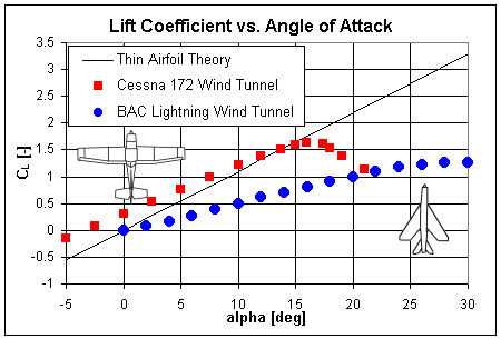
You'll be hard pressed to find design information for most aircraft as it is proprietary. On the other hand, lift coefficient is essentially linear with angle of attack; so long as you remain in a practical range. The slope of this linear portion is termed the "lift slope" and google can provide some good reading on that.

Furthermore, for academic purposes it is easiest to work with thin airfoil theories. In the case of a thin airfoil, the lift slope is 2pi. Again, you can google 'thin airfoil theory' or 'thin airfoil lift slope' and find some good reading/graphs. (Unfortunately much of it is riddled with calculus..but if you enjoy that kind of thing...) Here is an example photo:

lift-tat.gif
 
I realize this is probably a drawn out subject, but I could really use a better understanding of the relationship between flight path angle, aoa, attitude, and glide path (slope)...

Waterskiing. Pause for a moment and picture a man water skiing. With that mental image consider the following:

  1. Ski's are the wing. Being thin their chord line is easily imaginable.
  2. The water represents the relative wind, and in this 2D representation, also the flight/glide path.
  3. The angle between the ski's and the water represents angle of attack.
With the above mental image securely fixed in our brains we can begin to understand how angle of attack and speed correlate. What happens as the water skier is first pulled off by the boat? Going very slow he angles his ski tips way back (big angle of attack). As speed builds up his skis flatten relative to the water (smaller angle of attack).

Taking this a step further, what about when he's done performing and let's go of the rope? Starting at a high speed, his skis will be at a low angle. With the boat no longer supplying the power, drag will begin to overcome him and speed will slowly bleed away. As this happens the ski's angle of attack continues to increase until finally there isn't enough speed left. His ski's are now beyond critical angle of attack and subsequently he stalls and sinks.

Now that we, hopefully, have a great mental image of how speed, angle of attack, and stall interact; let's play with this flight path idea. First, let me tell you that flight path and glide path are the same thing. The word glide merely tells us that we are in a power off flight condition.

Alright, now that that is handled, go back and reread our 3 item list above and refresh this water skiing mental image because we are about to take it and break all scientific law with it! The water is the flight path and the relative wind, yes?

Well, what if the top of the water could be imagined as a string that we are holding taught between our two hands? The man skiing on the water will remain at his current speed, with ski's at their current angle of attack (angle relative to the water/string), and we can imagine rotating this string. We are breaking scientific law and imagining that we, the gods we are, can tilt water! eek

If we can do this we can affix a great mental image of how AOA and flight path work. Say we tilt the string (top of the water remember) to a 15 degree angle relative to earth. The skier remains on top of the string/water with his ski's at the same AOA remember. The difference now is he is skiing up hill at a flight path angle of 15 degrees, but still at the same arbitrary angle of attack that we first imagined him having.

With the above we can now define attitude and flight path:

Flight path: The path the aircraft is actually traveling relative to the surface of the earth.

Flight attitude: The angle of the flight path PLUS the angle of attack will give you the aircrafts pitch attitude relative to the surface of the earth. For example: Descending at a 5 degree angle (-5) plus flying at a 12 degree angle of attack (+12) gives a pitch attitude relative to earth of 7 degrees. (-5 + 12 = 7)


I believe that non-technically wraps up each of your questions. Hope I didn't hurt anyones feelings by breaking laws of physics with my imagination. Happy holidays JC. :)
 
Back
Top